american gas & chemical co. ltd.
 D E T E C T I O N   T E C H N O L O G Y


HOME | Products  |  Leak Detection  |  Plant Maintenance  |  Metal Integrity  |  Glossary  |  Safety  |  Gas Monitoring  |  Personnel Protection  |  Contact Us


  Plant Maintenance Technology
Sonic 3000 Ultrasonic Detector
 
How to Locate Leaks Using the Air Probe
There are many procedures for ultrasonic leak testing.
3000ap.jpg (5214 bytes)

The Basic Technique
To avoid following apparent leaks from sound beams bouncing off of walls, leak testing an operating system begins at the door to the room. After scanning the room, the direction of the most intense noise is followed to its source. Earphones are most often used because they block out background noise and they provide the most sensitive audio output.

Pressure Vessel Testing   (excerpted from the ASTM Standard Method)
Openings
Seal all openings using plugs, covers or other suitable materials which can be readily and completely removed after the completion of the test.
A gas inlet shall be provided by attaching a valve to one of the test covers on all items pressurized.

Check of Test Parts
Examine the part and test equipment before pressure is applied to insure that it is tight and all appurtenances that should not be subjected to the test pressure have been disconnected or isolated by valves or other suitable means.
Check safe pressure rating to be sure it will not be exceeded during test.

Temperature of Vessel and Testing Medium
The temperature of the pressurizing gas must not be at a level which would be injurious to the part or its components.
The test gas should be dry nitrogen or the standard calibrating gas (AGC Part # 3000CB) (Compressed air can contain oil droplets which can seal leaks).

Pressure
Unless otherwise specified the gauge pressure shall be at least 70kPa (10 psig). The pressure shall be gradually increased in the part to final test pressure.

Search
Search for leakage by pointing the probe at the test assembly and moving the probe around suspected leak areas.
Note the fluctuations in meter readings and the volume from the speaker or earphones.
When fluctuations are noted, maximize the meter reading by moving the probe and pointing it straight at the suspected leak area. The leak will generally be located in front of the probe when the meter reading and volume are at a maximum.

Location
To locate the leak, attach the rubber or focusing extension to the probe. This increases the directional response characteristics of the probe.
Keep the probe pointed in the direction where the meter indication and noise are maximized and move the probe toward the test assembly. Where the extension tip meets the test assembly (with maximum meter reading and noise), the leak is located.
It may be necessary to lower the volume control to keep the meter reading on scale as the probe is moved closer to the test assembly.

Locating Large Leaks
When leaks are discovered which are large enough to peg the meter's needle, the gain control should be lowered so the needle is about half scale. If leaks are approached with the meter at full scale the ultra-sensitive sound function of your instrument may flood making it more difficult to precisely locate the leakage source. 


How to Locate Leaks  Using the Contact Probe
 

3000cp.jpg (4582 bytes)

The contact probe is valuable for locating internal leakages of water, air, hydraulic fluids, or steam within piping systems. Small leaks can remain intermittent for some time but at some threshold point (about 150 milliliters per minute per inch of pipe for water) begin to grow rapidly making repair more difficult and costly.

Steam Traps and Valves
Steam leaks can be the most destructive and most rapidly growing. As a result all seals, valves and traps along piping systems should be monitored on a regular basis. Because of the high energy level of steam trap leaks the Sonic 3000 should be set initially at about half of normal calibration sensitivity. The remaining leak types should be monitored with the Sonic 3000 at the same sensitivity setting used with the air probe at full calibration.
After setting the Sonic 3000's gain, a survey should be conducted of similar valves and traps, listening carefully to the sound and recording the meter readings. Fluid leakage will be evident as a strong rushing sound and higher than normal meter readings. It is important to use the same spot on large valves when testing, however, on small valves and traps the probe is so sensitive that this may not be necessary.
The contact probe has a high and low sensitivity setting. (The red dot indicates high.) Low pressure steam settings usually require the high setting, while high pressure steam or excessive pipe vibration may be more easily checked with the low sensitivity setting.
The degree to which a trap is operating can be estimated by first placing the contact probe on the inlet side of the piping and adjusting sensitivity to 100% of full scale deflection on the meter. When the probe is placed on the discharge side of the trap, the Sonic 3000 meter reading will tell you the percent the trap opens and closes.  See also Steam Traps & Valves

Behind Walls or Under Cement
Leaks along piping, behind walls and under the floor can often be found without breaking the cement. By starting the contact probe at the point where the pipe comes to the surface and touching the cement every few feet along the pipe's course - leaks can be heard.

How to Locate Leaks Using the Transmitter      3000sg.jpg (7520 bytes)

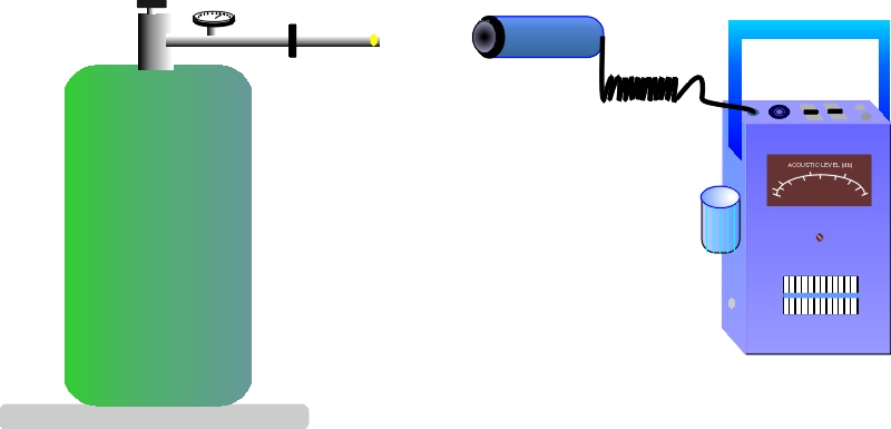
The Sonic 3000 transmitter is used to generate acoustic waves inside containers which are difficult to pressurize such as piping systems, tanks, large refrigerators, airplane cabins, window leaks, and condenser tubes.
The high energy waves of the transmitter flood the area and escape through small leaks in the same way that air would. The Sonic 3000 detects these waves easily which are heard as a shrill tone, unlike any other sound on the instrument. By following the sound to its source with the air probe, leaks can easily be located.
By increasing the number of transmitters in condenser tubes, the ultrasonic waves have been found sufficient to vibrate thin spots in the metal which are not yet leaks but will be soon.


How to Detect Machine Problems Using the Contact Probe 3000cp.jpg (4582 bytes)

The Sonic 3000 can help prevent unscheduled shutdowns in all types of rotating or reciprocating machinery by detecting the following types of faults:

  • Insufficient oil film
  • Oil whirl
  • Bearing problems
  • Gear defects
  • Misalignment
  • Bent or unbalanced shafts
  • Rubbing

PROCEDURE
It is important to measure the ultrasonic readings as closely as possible to the point of possible problems. It is also important that the same monitoring point should be used consistently. Because of the wave guide this surface need not be smooth or flat. It can be any temperature.
After calibrating the Sonic 3000, record the meter amplitude at each test point. Repeat this procedure in a week to assure repeatability, then again in one month. After this, readings should be taken periodically and recorded. Often a chart format is the easiest to use. Each machine is sufficiently different and a separate record should be kept on each one. There is not a universal norm. Stability of your readings is your best indication that no failure is in progress. Even gradual increases in readings are indicators that problems are developing.

USING THE SOUND FUNCTION
When the ultrasonic frequency is translated into audible sound good bearings have a distinct soft rushing sound. A louder grinding or crackling noise indicates the bearing is beginning to fail, whereas a gradual rise in the meter reading accompanied by a smooth rushing sound indicates possible lubrication failure.

STARTING A MAINTENANCE PROGRAM

  • Select the machines to be monitored.
  • Prepare a master sheet on each machine.
  • Choose the monitoring points on each machine and mark them.
  • Calibrate the Sonic 3000 and take initial readings. Be sure the machine operating conditions are recorded.

AFTER OVERHAUL:
Readings should be rechecked to verify all problems have been solved. Readings should return to machine norm.

NEW MACHINE-INCOMING INSPECTION
When purchasing new machinery, maximum acceptance levels should be established by checking your machines or others at the manufacturer prior to acceptance.

PRODUCTION QUALITY CONTROL
Manufacturers can institute routine measurements and establish acceptable levels for their own quality assurance and as an aid to customers maintenance programs and in field troubleshooting.


How to Locate Electrical Leakage          3000ap.jpg (5214 bytes)
3000fe.jpg (4099 bytes)

High voltage electrical corona arcing, insulation breakdown, and bad motor brushes, all produce strong vibrational energy with distinct audible characteristics:

  • Frying sound, ending in a click indicates a contact arc.
  • Continuous frying sounds indicate internal corona.
  • Build-up of frying sounds indicate progressive deterioration. If followed by silence, capacitor breakdown at a specific voltage is indicated.
  • A continuous AC hum indicates a good transformer.

Electrical problems are usually investigated with the air probe and the focusing extension so corona is easy to spot at a safe distance (usually about 3 feet) or when inspecting overhead wires outside.

The contact probe is sometimes used when airborne corona discharges are interfering or when the problem area is inside an enclosure. In these cases precautions need to be taken such as:

  • a high rated insulating glove.
  • standing on an insulated rubber pad.
  • an electrically insulating tip rigidly attached to the wave guide end.

During controllable inspections the voltage across the test component is gradually raised from zero to the peak test voltage. As the voltage is increased, the intensity and type of noise detected will change indicating the type and extent of problems.


Air Probe Calibration
.
     3000ap.jpg (5214 bytes)

The instrument must be calibrated before each initial use.  ASTM's "Standard Method of Testing Leaks Using Ultrasonics"  (ASTM E-1002 Standard Test Method for Leaks Using Ultrasonics)  requires the following calibration procedure and apparatus:

  • A leak standard with a preset flow rate of 1 centimeter per second ± 5%. The orifice size shall be approximately 5 mils.
  • A regulator for the calibration gas supply with a tank pressure gauge.
3000cal.jpg (44142 bytes) The detection probe shall be located at a distance of 10.0 meters (+ or - .1 meters) from the calibrated leak. Check to see that the detector probe and leak source are aligned. Adjust the instrument's meter to a meter reading of 50% of full scale.
 
Place a sound absorbing barrier in front of the microphone, blocking out the calibrated leak source; the meter reading should zero with a corresponding absence of an audible signal.

Recalibration
During inspection, the equipment must be periodically recalibrated at least once every four hours during use. This periodic recalibration must be performed using the reference leak to determine whether the leakage continues to trigger the monitoring system.

The equipment should be rechecked after any abnormalities have been observed in its operation.

American Gas & Chemical offers as an option (Part #3000CB) a calibration standard which meets the requirements of ASTM. The ASTM Standard Method is available upon request from American Gas & Chemical.


Site Map  

Copyright ©2023 American Gas & Chemical Co. Ltd., 220 Pegasus Avenue, Northvale, N.J. 07647-1977, U.S.A. 1-800-288-3647 or 1-201-767-7300 * fax: 201-767-1741 * purchase products from: https://detectorbuy.com